TechSepGaz mark TechSepGazGas–liquid separation engineering Separator sizing online
RUEN

Compact separators and engineering calculations

Engineering for the oil and gas industry. CFD modeling, 3D printing, prototyping and reverse engineering for the design and validation of separation equipment.

GLCC operating principle. Schematic based on the simulation model geometry, diameters scaled up 3×

Services

Calculation and manufacturing under one roof: simulation results can be checked on a physical model right away, without bringing in a second contractor.

Process equipment modeling

We build a simulation model of the unit from drawings or a 3D model and analyze it under operating conditions. The model shows what happens inside where measurements are not possible.

Applications: separators, cyclones, inlet devices, vessel piping

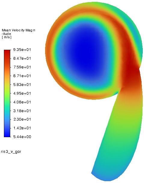
Examples of simulation results

Process and fluid dynamics calculations

Velocity and pressure fields, pressure drop, pulsation zones, phase distribution in multiphase flow. The output is visualizations and numerical values you can rely on when refining the design.

Applications: gas–liquid flows, selection and verification of internals

Size a separator online

3D printing and prototyping

We produce prototypes, functional parts and tooling from ready-made models or drawings: from small precision parts to housings up to 800×800×1000 mm in one piece.

Materials: PETG, PETG-CF, ABS, PA6, PC, PLA

Printers and printed parts

3D scanning and reverse engineering

We digitize parts that no longer have drawings, including black and glossy surfaces. We reconstruct the geometry and deliver a CAD model for manufacturing or analysis.

Applications: spare part restoration, dimensional inspection

Scanner and workstation

Separator sizing online

Two calculators: a two-phase gas–liquid separator and a three-phase gas–oil–water separator. Each sizes vertical and horizontal vessels from the same input data and compares them.

  • Diameter from the GOST 9617-76 standard series, overall dimensions and nozzles
  • Allowable gas velocity by Souders–Brown with pressure correction, droplet settling and trajectory
  • For three-phase: oil–water separation, overflow weir or water boot
  • ρv² checks on nozzles and mist eliminator flooding
  • Scale sketch and a summary for a technical proposal
4642 Ø1800 Gas, DN 350 Mist eliminator Inlet, DN 300 Liquid level Liquid, DN 40
Two-phase calculator result for the example case: 6.8 MPa, 30 °C, gas 170,000 Sm³/h, liquid 3 m³/h, wire-mesh mist eliminator. Vertical vessel, dimensions in millimeters.

What simulation results look like

Velocity fields and phase distribution show what happens inside the unit and provide the basis for design improvements.

GLCC compact separator, our own development

The gas-liquid cylindrical cyclone (GLCC) is a vertical pipe-based unit with a tangential mixture inlet. The phases separate in the centrifugal field of the swirling flow, so the unit is several times smaller and lighter than a gravity separator of the same capacity.

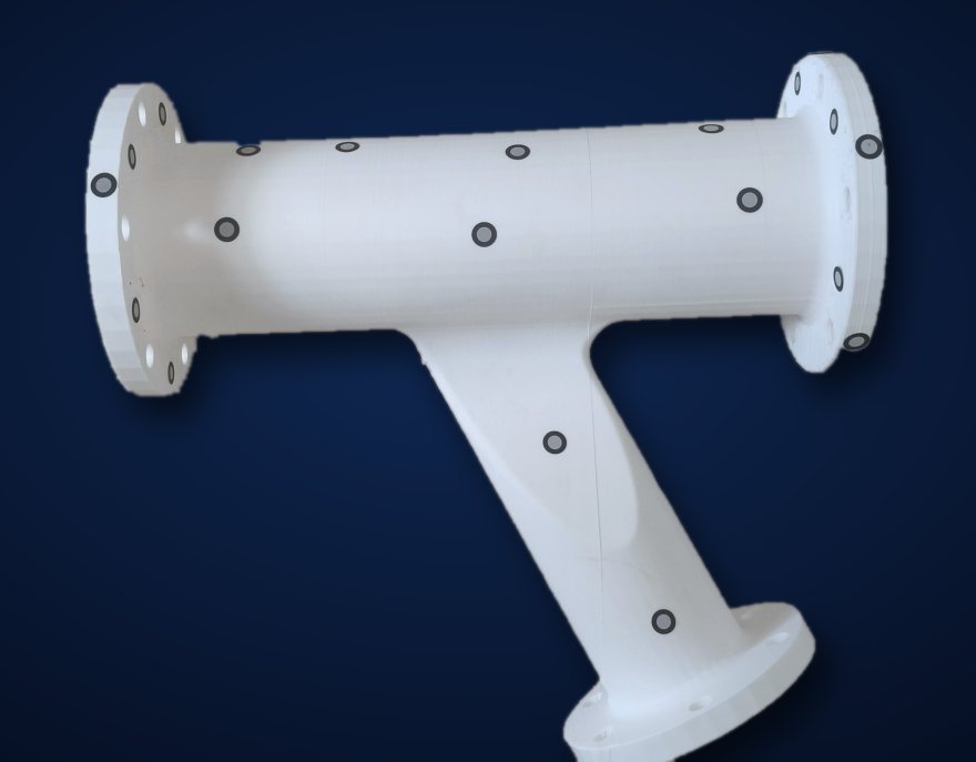
GLCC laboratory prototype: transparent body, inclined section and riser pipes, white 3D-printed parts at the flanges
GLCC laboratory prototype. Position numbers match the operating principle steps below.

Applications

  • Remote wells
  • Well testing and metering units
  • Space-constrained sites
  • Offshore facilities

Advantages

  • Smaller footprint and less steel
  • No moving parts
  • Simple pipe construction
Top view at the inlet level: the crescent nozzle gathers droplets into a film, liquid moves to the wall, gas to the center

Operating principle

  1. Upward flow in the riser

    The gas-liquid mixture rises through the vertical pipe to the bend.

  2. Inclined section

    The flow stratifies: liquid runs along the bottom of the pipe, gas flows along the top. The inclination angle is determined by calculation.

  3. Crescent nozzle

    The converging section accelerates the flow: droplets gather into a film and enter the body tangentially to the wall. This creates the swirl.

  4. Swirling flow

    Centrifugal force throws the liquid to the wall, and it flows down in a spiral.

  5. Gas outlet

    Gas collects in the vortex core, rises and leaves through the upper outlet.

  6. Liquid outlet

    Degassed liquid leaves through the bottom nozzle. The rotation forms a funnel on its surface.

How we work

  1. Brief

    We discuss the required outcome and collect input data: drawings, a model or a sample, operating conditions.

  2. Estimate

    We define the scope, timeline and cost. Work starts once these are agreed.

  3. Model

    We build a simulation or CAD model. If there are no drawings, we scan the part.

  4. Analysis or manufacturing

    We run the calculation or print the part and share interim results along the way.

  5. Result

    We deliver a report with field plots and recommendations, or the finished part, and answer questions after handover.

In-house equipment

Calculations, printing and scanning are carried out on our own equipment, without passing orders to third parties.

Bambu Lab H2DDual extruder, multi-material printing
Small and medium precision parts, assemblies with soluble supports.
Elegoo OrangeStorm GigaBuild volume 800×800×1000 mm
Housings and large assemblies in one piece, without gluing sections together.
Creality Raptor ProHybrid 3D scanner
Digitizing parts, including black and glossy surfaces.
High-performance workstation
Meshing, simulation and CAD modeling.

Made on our equipment

Printing an elbow on the Bambu Lab H2D 3D printer
Printing an elbow on the Bambu Lab H2D
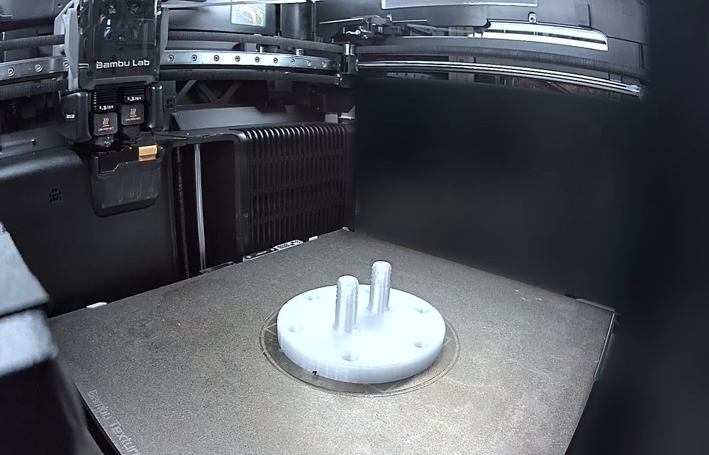
Printing a flange with nozzles
Printing a flange with nozzles
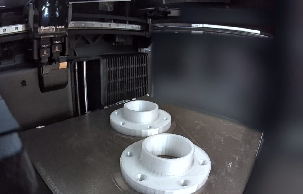
Printed flanges on the 3D printer bed
Flanges
Printed inlet assembly with flanges
Inlet assembly

Printing materials: PETG, PETG-CF, ABS, PA6, PC, PLA, HIPS, PVA. We select the material for the part's operating conditions. If a polymer is not suitable for the task, we say so before work begins.

Software

We use open-source packages that are widely applied in industry and research centers. Their licenses permit commercial use and do not tie the work to a single software vendor.

OpenFOAM
One of the most widely used open-source computational fluid dynamics packages in the world. Turbulent, multiphase and swirling flows.
ParaView
Post-processing and visualization of results: velocity and pressure fields, sections, streamlines, flow animation.
DWSIM
Chemical process simulator compatible with the CAPE-OPEN international standard: mass and energy balances, phase equilibria, fluid properties.

About the company

TechSepGaz is an engineering company based in Ufa, Russia. We develop compact separation equipment and perform engineering calculations for the oil and gas industry.

The company was founded in December 2025 and is supported by the Foundation for Assistance to Small Innovative Enterprises (FASIE) under the Student Startup program. Our own development is the GLCC compact separator (gas-liquid cylindrical cyclone).

Director
Ruslan R. Zinnatullin
Legal entity
TECHSEPGAZ LLC
Full legal name
OOO Tekhnicheskaya Separatsiya Gaza
TIN (INN)
0276185479
PSRN (OGRN)
1250200038252
Location
Ufa, Republic of Bashkortostan, Russia

Publications

Materials on gas-liquid separation and separation equipment calculations. The papers are published in Russian.

  • Conference paper

    Structure of the hydraulic resistance of a gas-liquid cylindrical cyclone

    What makes up the pressure drop in a GLCC at low liquid flow rates, and what this means for flow metering and level control.

    7th International Scientific Conference “Theory and Practice of Mass Transfer Processes in Chemical Engineering” (Marushkin Readings), Ufa

  • Article

    Development of a GLCC CFD model for pressure drop prediction

    How to build a simulation model of two-phase swirling flow in a cyclone and validate it against published experimental data.

    “TechnoEcoChemProcess-4.0” International Youth Conference, part of the Russian Oil and Gas Chemical Forum

Frequently asked questions

What tasks do you handle?

Calculation and modeling of process equipment, primarily separation equipment: separators, cyclones, inlet devices, piping. We also produce prototypes, parts and tooling on 3D printers, scan parts and reconstruct their geometry.

What do you need for a calculation?

Drawings or a 3D model of the unit and the operating parameters: phase flow rates, pressure, temperature, fluid properties. If anything is missing, we will tell you what else is needed.

How accurate are the online calculators?

The calculators give a first approximation of vessel dimensions for a technical proposal. They do not replace a strength calculation or a fluid dynamics analysis of the internals. Where the standard method may fall short, the calculators flag it.

Do I need my own 3D model to order printing?

No. A model can be built from a drawing or sketch, or obtained by scanning a sample part.

What is the maximum part size?

Up to 800×800×1000 mm in a single print. Larger items are assembled from several parts.

What materials do you print with?

PETG, PETG-CF, ABS, PA6, PC, PLA, HIPS, and PVA for soluble supports. We choose the material for the load, temperature and environment. If a polymer is not suitable for the task, we say so before work begins.

How much does the work cost and how long does it take?

Cost and timeline are determined from the technical specification after assessing the scope of work. Work does not start until the estimate is agreed.

Do you work with companies under contract?

Yes, we work with legal entities under contract. Calculations are carried out remotely, so the client's location is not a constraint.

Let's discuss your task

Describe the equipment and what needs to be done with it. We will tell you whether the task can be solved by calculation or manufacturing, and how long it will take.

Ufa, Republic of Bashkortostan, Russia. Pricing is based on the technical specification.